
NPT Thread Milling Macro
This article is covers an example of a national pipe thread (NPT) milling macro. If the reader is new to macro programming. It’s best to read Intro to Macro Programming and Advanced Macro Programming first.
This macro is similar to the helical interpolation macro, but helixes from the bottom up instead of top down. The reason we helix upward, is so the toolpath will climb-mill the thread. Conventional milling the thread would require helixing downward for a right-handed thread. The challenge we have here is that for an NPT thread, the helix radius must increase as we helix upward due to the thread’s taper. We cannot get a true tapered helix using arcs, but if we split the helix into quadrants, we can get a fairly decent approximation of a true tapered helix. This will be good enough for the NPT thread to seal as intended and pass inspection. This macro can do any taper, not just NPT, and can be altered to do any number of full turns to accommodate both multi-toothed threadmills or single-point threadmills. When using a multi-toothed threadmill, it is typical to only require one full turn of the helix, whereas a single-point threadmill requires a tapered helix all the way up to the top of the thread.
Figures 1-3 depicts the process
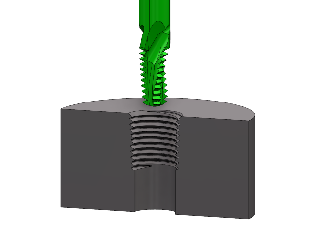
Figure 1:
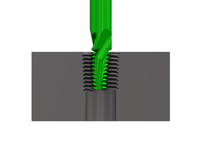
Figure 2

Figure 3: Thread Milling Tool Path
NPT Thread Milling Macro Example.
Here is the code with explanations that follow:
%
O1234
(MACRO FOR NPT INTERNAL THREADMILL)
(TPF FOR NPT IS 0.75")
#101=[0.540/2](THREAD OD AT TOP /2)
#102=[0.3125/2](TOOL CUTTING DIAMETER /2)
#103=[1/18](1/TPI - THREAD PITCH)
#110=8(# OF COMPLETE TURNS)
#104=[#101-#102]
#106=0.75(THREAD TAPER PER FOOT)
#105=[#103*#106/96]
G28 G91 Z0.
G28 G91 Y0.
G90
T1 M06
S4000 M03
G0 G90 G54 X0 Y0
G43 H01 Z-1.550
M08
G1 G90 Z-1.550 F50.(ADJUST Z DEPTH)
#111=#110
#112=[-1*#110*#105*4]
G1 G41 G91 D05 X[#104/2+#112/2] Y[#104/2+#112/2] F6.
G03 G91 X[-1*[#104/2+#112/2]] Y[#104/2+#112/2] I[-1*[#104/2+#112/2]] Z[#103/8]
WHILE[#111GT0]DO1
G03 G91 X[-1*[#104+#112+#105*1]] Y[-1*[#104+#112]] I0 J[-1*[#104+#112+#105*1]] Z[#103/4]
G03 G91 X[#104+#112+#105*1] Y[-1*[#104+#112+#105*2]] I[#104+#112+#105*2] J0. Z[#103/4]
G03 G91 X[#104+#112+#105*3] Y[#104+#112+#105*2] I0. J[#104+#112+#105*3] Z[#103/4]
G03 G91 X[-1*[#104+#112+#105*3]] Y[#104+#112+#105*4] I[-1*[#104+#112+#105*4]] Z[#103/4]
#111=[#111-1.]
#112=[#112+4*#105]
END1
G03 G91 X[-1*[#104/2]] Y[-1*[#104/2]] I0. J[-1*[#104/2]] Z[#103/8]
G01 G40 G91 X[#104/2] Y[-1*[#104/2+#112-#105*4]]
G0 G90 Z1.
M05
M09
G28 G91 Z0.
G28 G91 Y0.
G90
M30
%
Code explanations
The above code is broken into sections with bold text. Explanations in italics and brackets {} follow.
%
O1234
(MACRO FOR NPT INTERNAL THREADMILL)
(TPF FOR NPT IS 0.75")
#101 = [0.540/2] (THREAD MAJOR DIA AT TOP /2) {This variable is used to set our thread’s top diameter. It is divided by 2 to give the radius.}
#102 = [0.3125/2] (TOOL CUTTING DIAMETER /2) {This variable is used to set our tool’s diameter. It is divided by 2 to give the radius.}
#103 = [1/18] (1/TPI - THREAD PITCH) {This variable is used to set our thread’s pitch by calculating 1 divided by the threads per inch.}
#110 = 1 (# OF COMPLETE TURNS) {This variable is used to set the number of complete turns. 1 for threadmills that have enough teeth to complete the thread in one pass, multiple for single point thread mills.}
#104 = [#101-#102] {This variable is just a calculation of our thread’s top radius minus our tool’s radius to simplify the code for subsequent calculations. It is not to be changed by the operator.}
#106 = 0.75 (THREAD TAPER PER FOOT) {This variable sets the taper of the helix. It should be the same as the thread’s taper. In this case, 0.750” per foot for an NPT thread. Taper per foot is expressed as inches of diameter over one foot of length.}
#105 = [#103*#106/96] {This variable is a calculation of the increase in radius for each quadrant of the tapered helix. Thread pitch times the thread TPF, divided by 12 in/ft, divided by 2 to get radius, divided by the 4 quadrants (i.e. 12*2*4 = 96). It is not to be changed by the operator.}
G28 G91 Z0.
G28 G91 Y0.
G90
T1 M06 {Change to tool one}
S4000 M03 {Spindle at 4000 RPM forward.}
G0 G90 G54 X0 Y0 {Rapid to center of threaded hole.}
G43 H01 Z1. {Rapid to clearance height with tool length offset [H01]}
M08 {Coolant on.}
G1 G90 Z-0.550 F50. (ADJUST Z DEPTH) {Fast feed to the bottom of the thread.}
#111 = #110 {We will copy the number of complete turns (#110) to a temporary variable (#111) so we can subtract completed turns from this value as we helix upward, without affecting the original variable (#110).}
#112 = [-1*#110*#105*4] {This variable is a calculation of how much to reduce the helix radius initially for multiple helix passes to achieve the desired top diameter specified in variable #101. (-1 * Number of complete turns (#110) * radius increase per quadrant (#105) * 4 quadrants).}
G1 G41 G91 D01 X[#104/2+#112/2] Y[#104/2+#112/2] F6. {Here we start to use G91 (incremental coordinates) so the toolpath is relative to the centre position of the thread. G41 and D01 are used for cutter wear compensation, although the top diameter (#101) or tool diameter (#102) can also likewise be adjusted to achieve the same result. | Line ①}
G03 G91 X[-1*[#104/2+#112/2]] Y[#104/2+#112/2] I[-1*[#104/2+#112/2]] Z[#103/8] {Here we arc into the thread using half the diameter of the first quadrant, and 1/8th of the pitch to keep the helix angle the same as the four quadrants. | Arc ②}
WHILE[#111 GT 0]DO1 {Start while loop. Note that this is a “Do 1” and not a [D01] for cutter compensation. It will repeat the while loop for the number of complete turns (#110).}
G03 G91 X[-1*[#104+#112+#105*1]] Y[-1*[#104+#112]] I0 J[-1*[#104+#112+#105*1]] Z[#103/4] {First quadrant. Note that we increase the radius by [#105*1] and increase the [Z] position by a quarter of the pitch (Z[#103/4]). | Arc ③}
G03 G91 X[#104+#112+#105*1] Y[-1*[#104+#112+#105*2]] I[#104+#112+#105*2] J0. Z[#103/4] {Second quadrant. Note that we increase the radius by [#105*2] and increase the [Z] position again, by a quarter of the pitch (Z[#103/4]). | Arc ④}
G03 G91 X[#104+#112+#105*3] Y[#104+#112+#105*2] I0. J[#104+#112+#105*3] Z[#103/4] {Third quadrant. Note that we increase the radius by [#105*3] and increase the [Z] position again, by a quarter of the pitch (Z[#103/4]). | Arc ⑤.}
G03 G91 X[-1*[#104+#112+#105*3]] Y[#104+#112+#105*4] I[-1*[#104+#112+#105*4]] Z[#103/4] {Fourth quadrant. Note that we increase the radius by [#105*4] and increase the [Z] position again, by a quarter of the pitch (Z[#103/4]). | Arc ⑥}
#111 = [#111-1.] {Subtract one turn from our temporary variable (#111).}
#112 = [#112+4*#105] {Add the radius increase for the next full turn of four quadrants [4*#105]}
END1 {End the while loop when the number of complete turns (#110) is completed.}
G03 G91 X[-1*[#104/2]] Y[-1*[#104/2]] I0. J[-1*[#104/2]] Z[#103/8] {Here we arc out of the thread using half the diameter of the last quadrant, and 1/8th of the pitch (#103) to keep the helix angle the same as the four quadrants. | Arc ⑦}
G01 G40 G91 X[#104/2] Y[-1*[#104/2+#112-#105*4]] {Here we feed back to the centre of the thread, and cancel cutter compensation.}
G0 G90 Z1. {Here we go back to using G90 (absolute coordinates) and rapid to a clearance height (Z1.)}
M05 {Spindle off.}
M09 {Coolant off}
G28 G91 Z0.
G28 G91 Y0.
G90
M30
%
We hope this article provides another example from which to learn from. Amco is continually improving our processes and macro programming is one useful tool to help us. Contact Amco for your machined parts needs today.